The Printable Enclosure
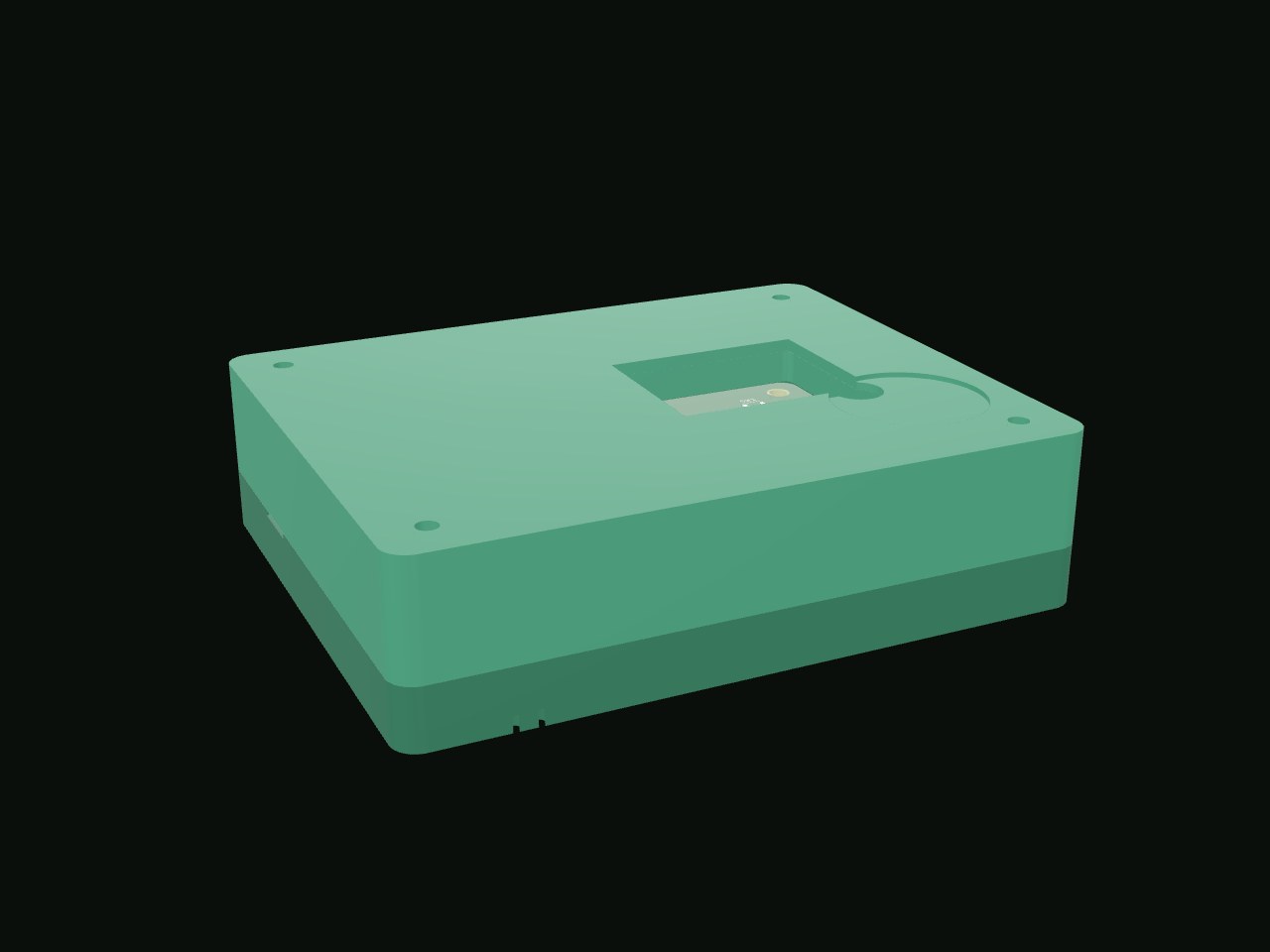
The enclosure is not drawn; it is generated. hardware/enclosure/safi_enclosure.py is a FreeCAD script that builds the whole two-part shell from a parameter block and exports STEP and STL. Run it headless and out come safi-enclosure-base and safi-enclosure-lid in both formats plus the FreeCAD document.
Why CAD as code
A hand-drawn enclosure and a PCB drift apart the moment either changes. When the board's USB-C connector moves 3 mm, a drawn enclosure needs someone to remember, find the cutout, and nudge it. This enclosure expresses every cutout in board coordinates (origin at the board's top-left, exactly as KiCad measures it) and maps them into the shell with one function. Move the connector in the PCB, change one line here, re-run, done. The geometry is reproducible, diffable, and reviewable in a pull request like any other source.
The trade-off is real: parametric Part-workbench code is less expressive than sketch-and-pad modeling, and organic shapes are painful. For a rectilinear project box driven by a rectangular board, that is exactly the right trade.
What it builds
A base and a lid that screw together:
- The base has a floor, four walls, and M3 standoff bosses at the board's exact mounting-hole coordinates (read straight from the KiCad positions), raising the board off the floor to leave room for through-hole pins and the back-side coin cell holder.
- Cutouts follow the board: a USB-C opening in the left wall, a microSD slot in the bottom wall, and a speaker grille (a ring of holes) through the floor under the amplifier's output.
- The lid carries the display window over the TFT, the encoder shaft hole, a shallow NFC tap recess that marks where to present a card over the PN532, and screw holes aligned to the bosses.
Walls are 2.4 mm, the fit clearance around the board is 0.3 mm per side, and the corners are filleted. The whole thing is designed to FDM-print without supports and assemble with four M3 screws.
The parameter block is the interface
Everything adjustable lives at the top of the script: board size and thickness, wall thickness, standoff height, headroom above the board, corner radius, and the board-coordinate position of each cutout. Printing on a machine with a tight first layer? Change the fit clearance. Using a taller display module? Change the headroom. The rest of the model follows because it is all derived, never hard-coded twice.
Sanity checks in the model
The script asserts what a silent bug would otherwise hide: both solids have positive volume (a failed boolean cut yields an empty shape), and the internal cavity is at least as large as the board footprint. These are cheap guards that turn a subtle modeling mistake into a loud failure at generation time rather than a part that does not fit after a four-hour print.
Printing and assembly
Print both parts in the orientation they are exported (base floor-down, lid top-down) for the cleanest cutouts and no supports. The user enclosure guide covers material choice, layer height, and the heat-set-insert option for the M3 bosses. The STEP files are there if you would rather machine it or drop it into a larger assembly.